Implementation Workspace — automated design review
Video transcript
00:04 — Upload the KiCad project
The Implementation Workspace reviews the design you actually built. Start a workspace for the board, here the PIC programmer from the KiCad demos. Then drop in the whole KiCad project. The worker runs KiCad itself: its electrical and design rule checks, the netlist, and a 3D export. Then the platform reviews the schematic and the board with its own rules and patterns. Moments later there is a schematic and a board, each with findings you can accept, reject or defer, and each finding says which tool raised it.
00:42 — Findings on the board
Open the board, and the findings are drawn where they are: on the copper layers, beside the part they name. Zoom in, and hover a marker to read the finding it stands for. And the board's own 3D model, exported by KiCad, is one click away.
01:03 — Thermal model
New in the workspace: a thermal model of the board. You declare the heat, watts per part, and a junction to board resistance where the datasheet gives one, with the ambient and the convection on each face. The worker meshes the board and solves it in Elmer, a finite element solver, then checks the energy balance, so a run that loses heat says so. Back comes the board maximum, the temperature under every loaded part, and a junction estimate where one was declared, each shown beside the inputs it rests on. Lay the heat map over the board layers to see where the heat goes. Bind the run to a temperature requirement and it becomes evidence: a pass, or a finding.
01:48 — Mechanical model
Also new: mechanical models. Upload a STEP file, here the enclosure panel the board screws to, and the worker measures it: its envelope, volume, mass and every hole. Because the workspace already holds the board, the fit check runs straight away, matching the board mounting holes to the holes in the panel.
02:12 — Enclosure fit
Here one mounting hole is a millimetre out. The hole pattern is symmetric, so the finding names both candidate holes rather than guessing one, and files it under mechanical engineering, before a single part is made. And the panel itself is there in 3D.
02:35 — One review
Schematic, board, heat and enclosure fit, reviewed in one workspace, with every finding traced to the evidence it came from, and the whole review exportable as a controlled document. A design review in minutes, not a meeting.
What it does
Every other tool in Creopus helps you produce a document. The Implementation Workspace does the opposite: you upload the design you have actually built — schematic netlist, PCB layout, SPICE deck — and it reviews it, producing structured findings against your own requirements and DFMEA.
It is a second pair of eyes that has read your requirements, at three in the morning, without getting bored on page forty.
Why it matters
Design review is where hardware teams lose the most time and catch the fewest problems. A senior engineer reads a schematic for an hour, spots six things, and misses the missing decoupling cap on page four because nobody can hold a whole board in their head.
The reviews that scale are the boring, deterministic ones — is every net driven, is the annular ring above the fab's floor, does the .tran window actually cover the RC time constant. Those should never have needed a human. What a human is genuinely good at is judgement, and judgement is what is left once the mechanical checks are done.
This is also the part of Creopus that no requirements tool does. Requirements platforms manage text about your design; layout tools work on the design but have never read your requirements. The Implementation Workspace sits in between.
What it reads
24 parsers, so it takes the files you already have rather than asking you to export something special:
- Schematic — KiCad (XML and legacy, multi-sheet), Altium
.SchDoc, Protel, Qucs, LTspice, QSpice - Layout — KiCad
.kicad_pcb, Gerber (RS-274X, zipped), Excellon drill, ODB++, IPC-2581, Altium.PcbDoc - Simulation — SPICE decks, Cadence Spectre
Format is auto-detected. Large files go to object storage rather than into the document.
How the review works
Three layers, each doing what it is actually good at:
Layer 1 — deterministic rules. 32 schematic rules, 14 layout rules, 13 simulation rules. Floating nets, multi-driver conflicts, outputs tied to power rails, trace width below the floor, annular ring, copper-to-edge clearance, unrouted nets, model references that do not exist, transient analyses with no transient source. These either fire or they do not — reproducible, explainable, no model involved.
Layer 2 — curated patterns. 29 schematic and 19 layout patterns encoding the things experienced engineers check by habit: LDO bypass caps, I²C pull-ups, crystal load caps, MOSFET gate resistors, decap proximity, via-in-pad, thermal-pad vias, mounting-hole isolation, real DRC clearance backed by spatial indexing, and copper pour imbalance computed from actual flood-fill area rather than an estimate.
Layer 3 — grounded LLM review. Only here does a model get involved, and only with your requirements, DFMEA, block diagram and BOM in front of it. It is asked to judge whether the implementation actually realises what those documents promised — the question a deterministic rule cannot ask.
There is also a cross-artifact pass that checks the schematic, simulation and layout against each other: do the references match, does the sim exercise the circuit that was drawn, does the layout implement the schematic.
What you get back
Findings, each with a severity (critical / major / minor / editorial), a category, the layer that produced it, a location, a recommendation, and a discipline tag (electrical / layout / mechanical) so the right person sees the right subset.
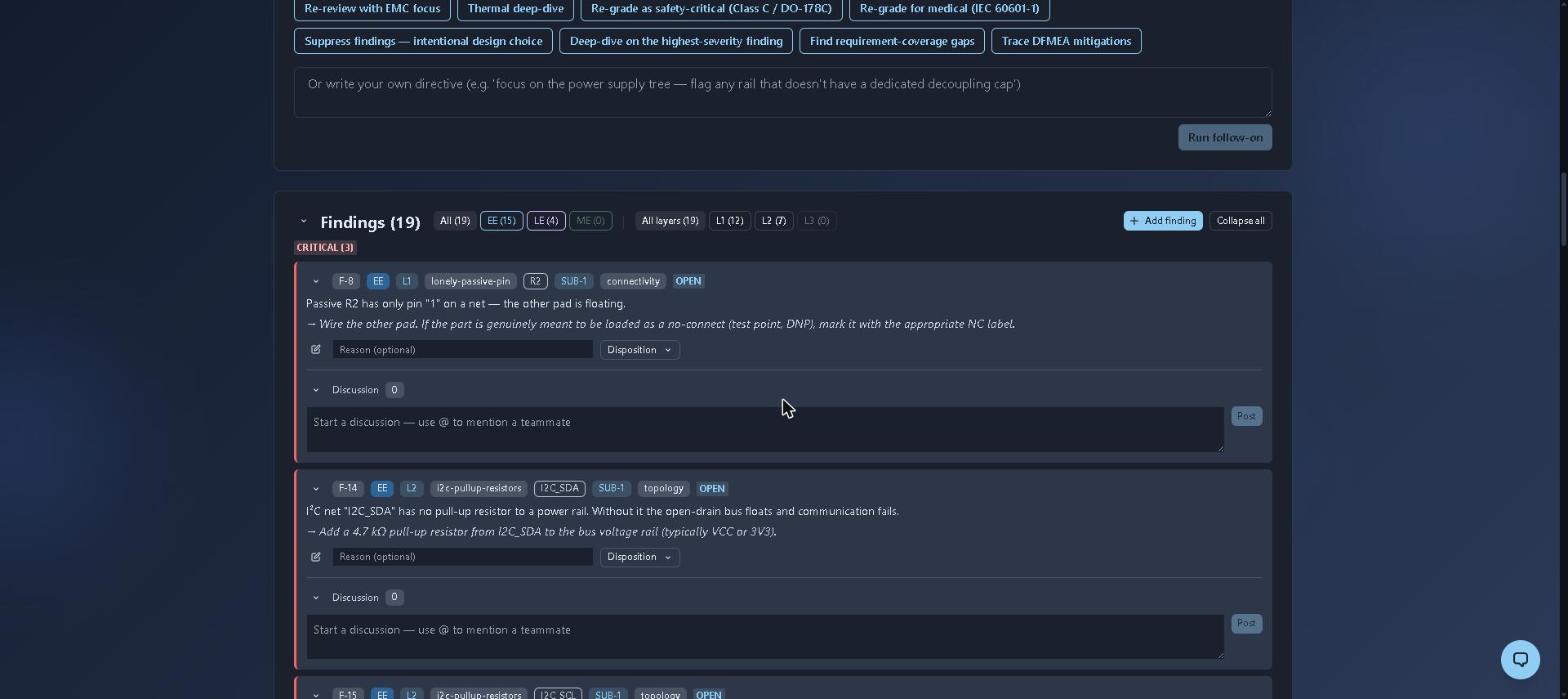
A real run against an 11-component, 14-net flight-computer schematic: 19 findings in a few seconds, 12 from deterministic rules and 7 from curated patterns. F-8 caught a resistor with one pad floating; F-14 caught an I²C net with no pull-up — an open-drain bus that would simply never communicate. Filter by discipline so layout engineers are not reading electrical findings, and dispose of each one like a review comment.
Findings are dispositioned like review comments — open → accepted / rejected / deferred / noted, with reason and audit fields — and each carries its own comment thread, so the EE-to-layout conversation lives with the finding instead of in a chat log. Findings can link to the specific requirement or DFMEA failure mode they relate to.
You can add findings by hand too. A manual finding is marked as human-authored, and that provenance survives editing, so "did a person or the machine flag this?" always has an answer.
Getting started
Create an Implementation Workspace on the hierarchy node whose design you are reviewing — the node context is what makes Layer 3 useful. Upload a schematic first; Layers 1 and 2 run immediately, and the LLM review runs in the background and appears when it completes. Add the layout and simulation as they exist, and the cross-artifact checks become available once you have more than one.