Block Diagram
Video transcript
00:04 — Block Diagram
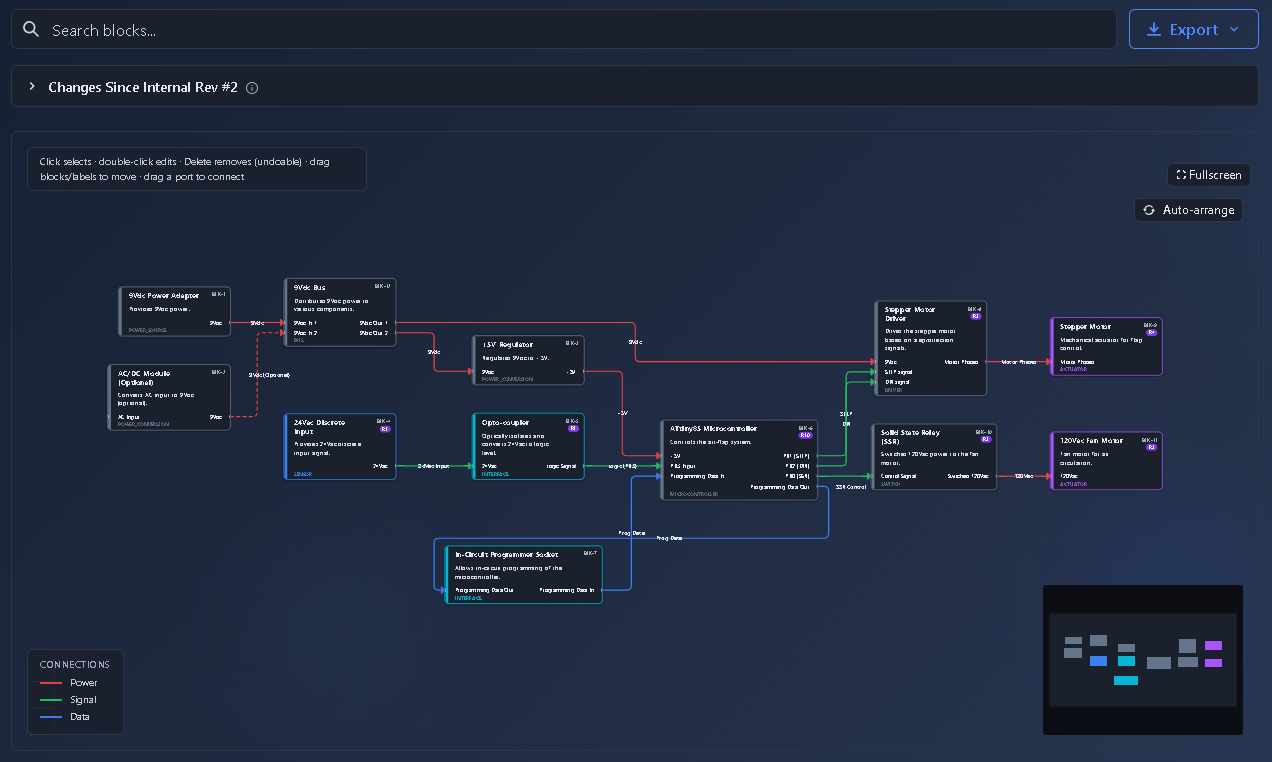
Capture the architecture with the agent’s help. Start a blank block diagram, then ask the agent to draft it from the board’s design — approving as it goes. It lays out each block’s inputs, outputs and the interfaces between them: the power, the microcontroller, the motor driver and the sensors, wired the way the real system is. And every block’s function can link to the requirements it implements, so the picture isn’t just a drawing — it’s part of the traceable model.
Typed blocks and connections — with a trade study on every block.
What it's for
The concept-phase architecture artifact. Blocks are typed (Sensor, Processor, Actuator, Power, Interface, Memory, Custom) with input/output ports; connections are typed (data/signal/power/control/bidirectional) and styled. It renders three ways — an SVG canvas, a System Blocks table, and a Connections table — and every block carries a Trade Study action that launches a scoped Pugh matrix.
When to use it
Concept phase, once requirements exist. Drives the BOM, the ICD, and per-block trade studies.
How it works
-
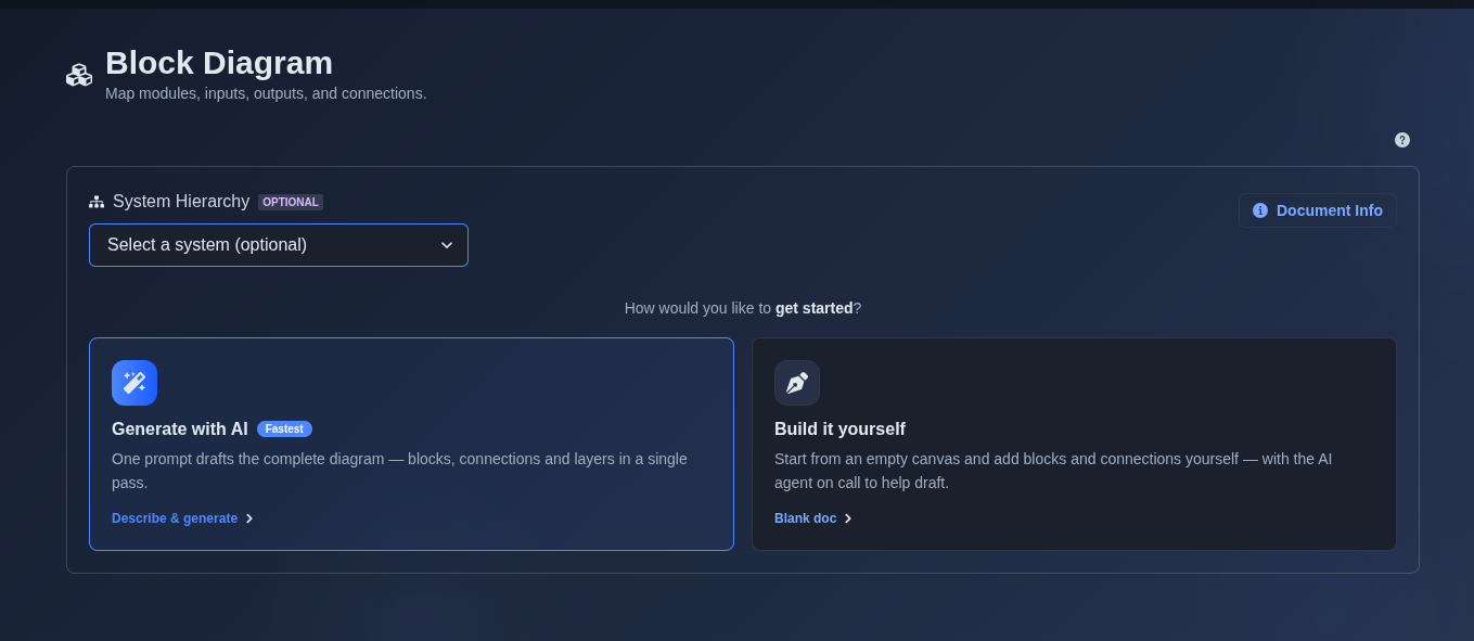
Select Generate with AI or Build it yourself. → First, select whether you want to “Generate with AI” or “Build it yourself”; selecting a system is optional for both options. If “Generate with AI” is selected, describe your project, requirements, or the block diagram you want to create in the prompt and run it. The AI analyzes the prompt and automatically generates the required blocks and connections. If “Build it yourself” is selected, choose “Create a blank document” to open an empty canvas, then manually add, arrange, and connect the required blocks.
▶ Initial State▼ Initial State
-
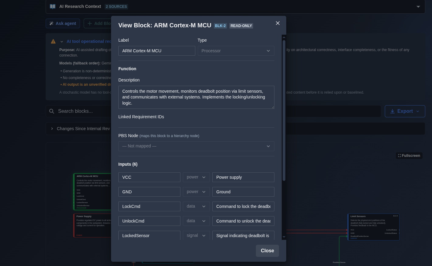
Click a block for the Block Editor; click a connection for the Connection Editor. → Double-click a block to open the Edit Block option, then edit the label, type, function, description, linked requirement IDs, PBS node, inputs, and outputs as needed. You can add or remove inputs and outputs and update their names, types, and descriptions. For AI-generated block diagrams, editing requires Follow-on mode.
▶ Edit Block▼ Edit Block
-
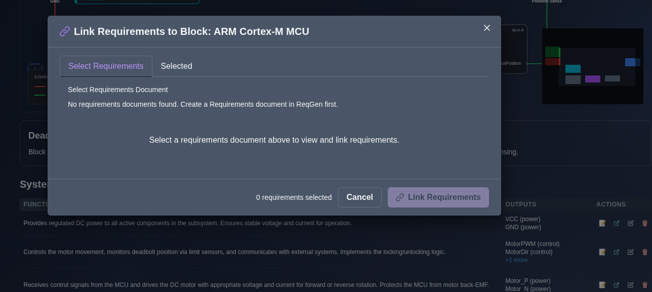
Link requirements and map the block to a PBS node. → Add requirement IDs to link relevant requirements to the block, and use the PBS Node picker to map the block to the corresponding hierarchy node. The linked requirements and PBS mapping are saved with the block.
▶ Link Requirements▼ Link Requirements
-
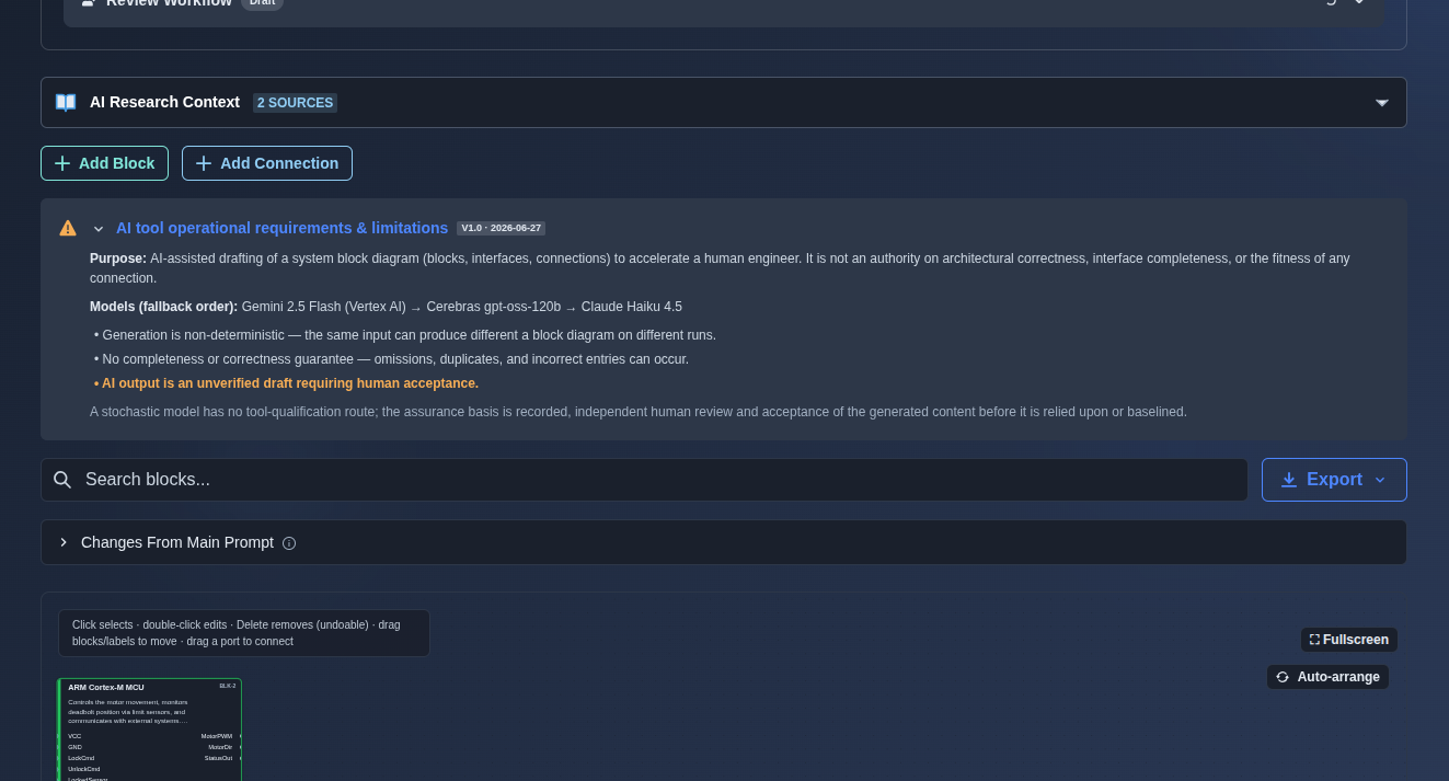
Add a new block or connection. → Click “Add Block” to add a new block to the diagram, or click “Add Connection” to create a new connection between blocks. Configure the required details, and the new block or connection is added to the diagram.
▶ Add Block or Connection▼ Add Block or Connection
-
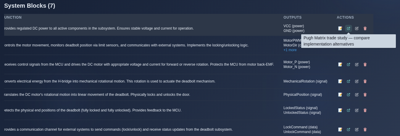
Click a block’s Trade Study action. → The Trade Study opens a Pugh matrix using the selected block’s function and I/O as the initial context. You can compare alternatives against defined criteria and identify the preferred option. A 🏆 tag marks blocks that already have a selected trade-study winner.
▶ Trade Study▼ Trade Study
-
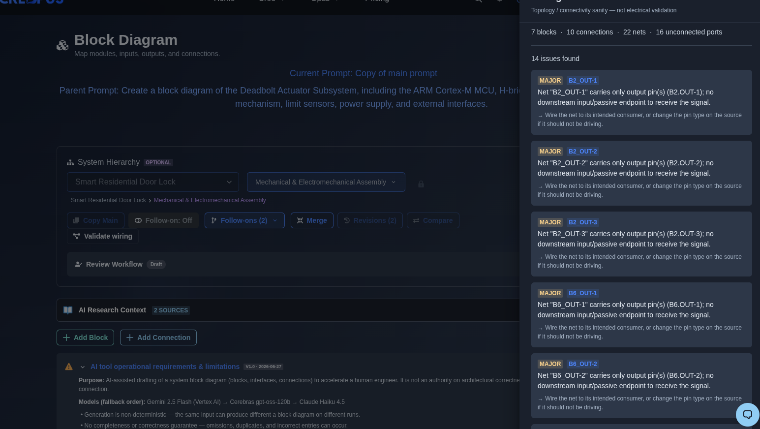
Run Validate wiring. → The tool checks the block connections and identifies wiring issues such as multiple drivers, floating inputs, dangling outputs, and excessive fan-out. Detected issues are displayed with severity indicators as a connectivity check, not an electrical simulation.
▶ Validate Wiring▼ Validate Wiring
-
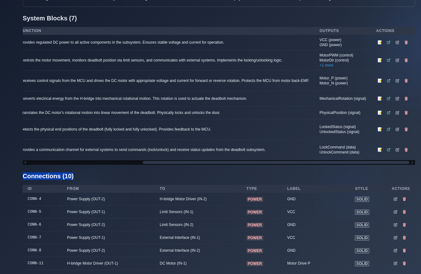
Manage blocks and connections from the System Blocks and Connections tabs. → The System Blocks tab provides actions to link requirements, open the Pugh Matrix/Trade Study, edit, or delete each block. The Connections tab provides actions to edit or delete each connection. Deleted items can be undone or restored from the Removed-Items panel.
▶ Manage System Blocks and Connections▼ Manage System Blocks and Connections
-
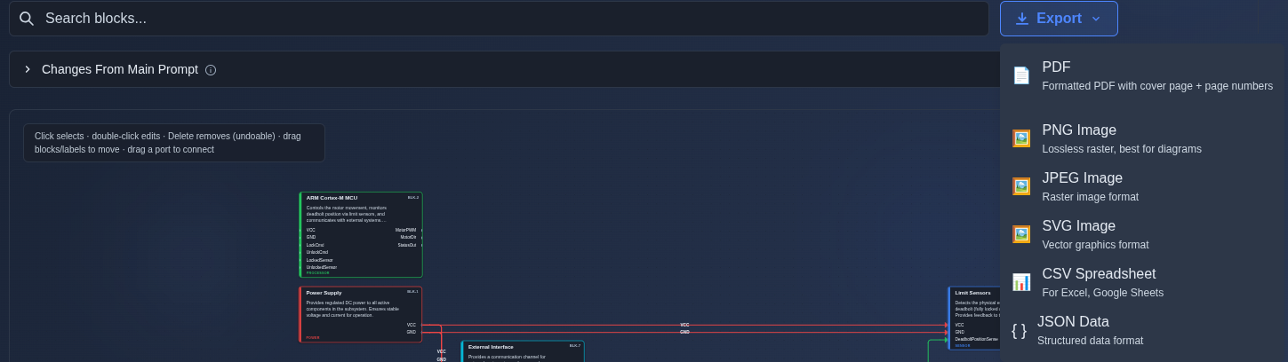
Export the block diagram. → Click “Export” and select the required format: PDF, PNG Image, JPEG Image, SVG Image, CSV Spreadsheet, or JSON Data. The block diagram is exported in the selected format.
▶ Export▼ Export
Mechanics
- SVG canvas + System Blocks table + Connections table · fullscreen
- 7 block types · typed/styled connections · port-level wiring
- Block Editor / Connection Editor · Block Library · Auto-arrange
- Requirements-Import linking · PBS-node mapping
- Per-block Trade Study → scoped Pugh · Validate-wiring check
- Hard delete with Undo · Removed-Items restore panel
- Export: PDF · stamped PDF · PNG · JPEG · SVG · CSV · JSON