System Hierarchy
Video transcript
00:04 — System Hierarchy
Every artifact in Creopus — requirements, FMEAs, verification plans, bills of materials — attaches to a node in your product hierarchy, a five-level V-model from the system down to a subassembly. Here is the whole smart door lock as one tree. Click any node — the Main Control Board — and a full engineering workbench opens: its V-model properties, the requirements derived at that level, every attached artifact, and the verification coverage matrix — the traceability health for that node and everything under it. One connected model, from the system down to the last component.
The recursive V-model system-of-record everything else hangs on.
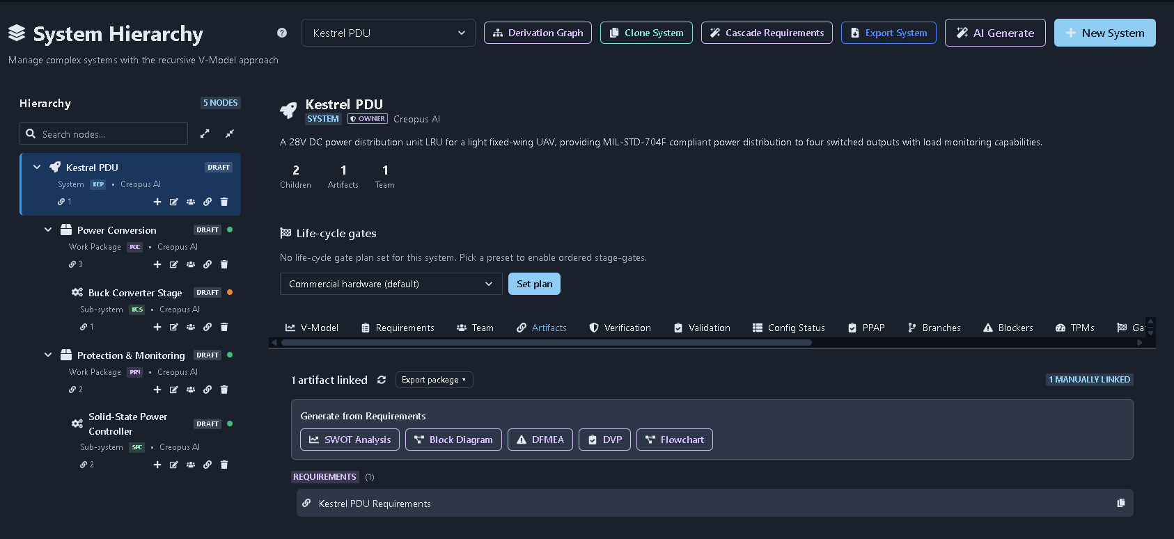
What it's for
The backbone of the system engineering workspace. It provides a recursive V-Model hierarchy from System → Work Package → Sub-system → Assembly → Sub-assembly, with each node carrying its own status, lifecycle gate plan, team access, artifacts, and engineering activities. From each node, users can manage requirements, team members, artifacts, verification, validation, configuration status, PPAP, branches, blockers, TPMs, gate reviews, and baselines. The system also supports AI generation, cloning, cascading requirements, derivation tracking, and exporting the system structure.
When to use it
Use the System Hierarchy at the beginning of a project to establish the overall system structure. Create the system and organize its work packages, sub-systems, assemblies, and sub-assemblies so that requirements, artifacts, verification, validation, and other engineering activities can be managed within the appropriate node.
How it works
-
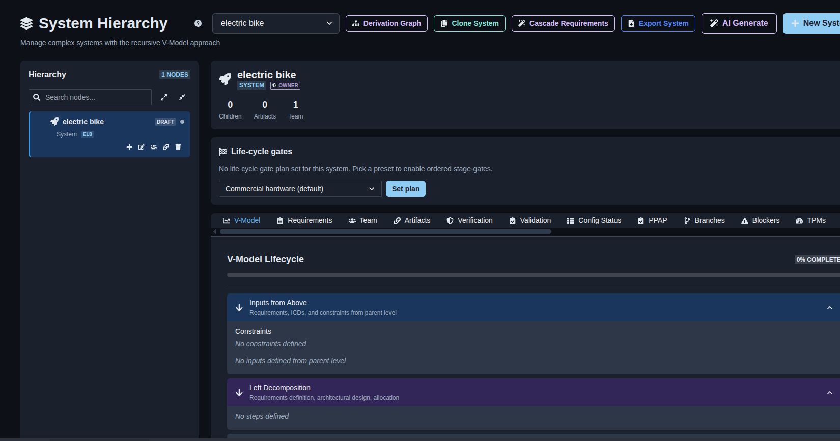
Create a new system. → Click “New System” and enter the System Name, Description, Owner Company (OEM), and Breakdown structure (PBS depth). Click “Create System” to create the system and open its System Hierarchy workspace.
▶ Create new system▼ Create new system
-
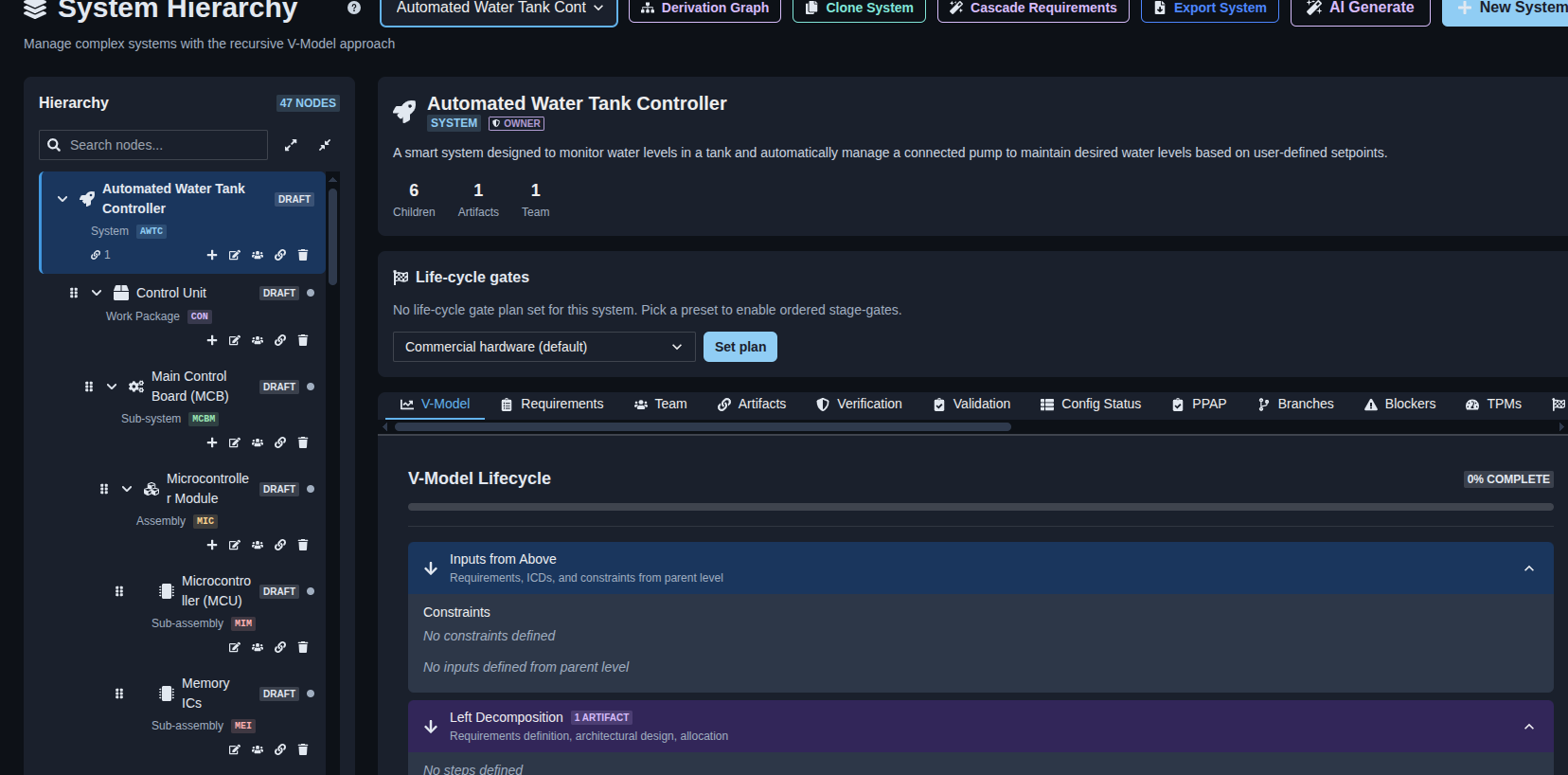
Generate a system hierarchy with AI. → Click “AI Generate,” enter the Product / System Description and optionally the Owner Company, then click “Continue.” Review the proposed hierarchy, edit node names or structure as needed, add or remove child nodes, and click “Create System” to generate the hierarchy. After the system is created, click “Generate Requirements for All Nodes,” review the generated root requirements, and click “Continue cascade to all children” to generate requirements for the child nodes.
▶ Generate wwith AI▼ Generate wwith AI
-
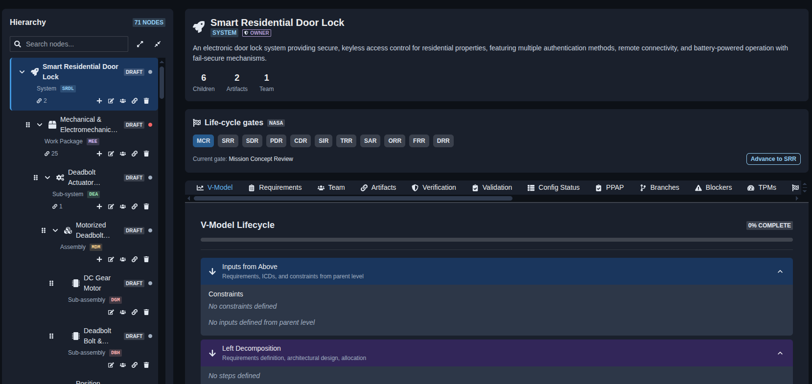
Manage system hierarchy nodes. → Use the node controls to manage the hierarchy. Click “Edit” to modify a node, “+” to add a child node, the Team icon to manage team members, the Link icon to manage node links, and the Delete icon to remove a node from the hierarchy.
▶ System hierarchy nodes▼ System hierarchy nodes
-
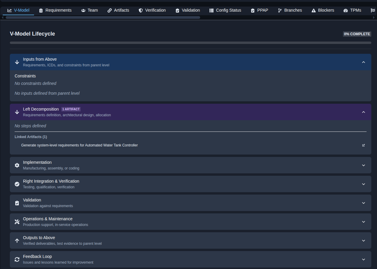
Review the V-Model lifecycle. → Review the V-Model lifecycle for the selected system, including Inputs from Above, Left Decomposition, Implementation, Right Integration & Verification, Validation, Operations & Maintenance, Outputs to Above, and Feedback Loop. Expand each section to review its related requirements, artifacts, implementation activities, verification and validation information, deliverables, and feedback.
▶ V-model▼ V-model
-
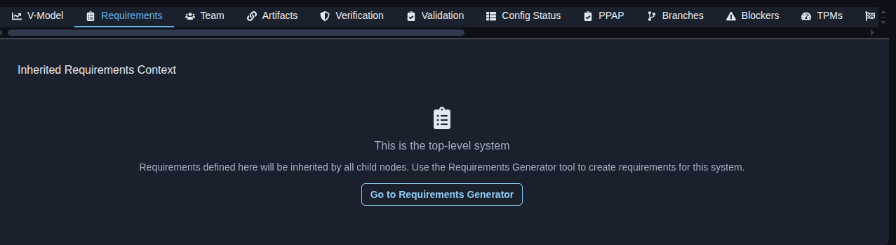
Requirements. → Open the “Requirements” tab to review the inherited requirements context for the selected system. For a top-level system, requirements defined at this level are inherited by child nodes. Click “Go to Requirements Generator” to create requirements for the system.
▶ Requirements▼ Requirements
-
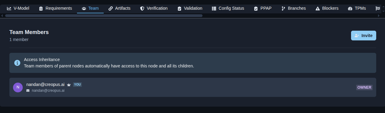
Team members. → Open the “Team” tab to review the team members who have access to the selected system. The tab shows the total number of members, each member’s name, email address, and role, and indicates inherited access from parent nodes. Click “Invite” to invite additional team members to the system.
▶ Team member▼ Team member
-
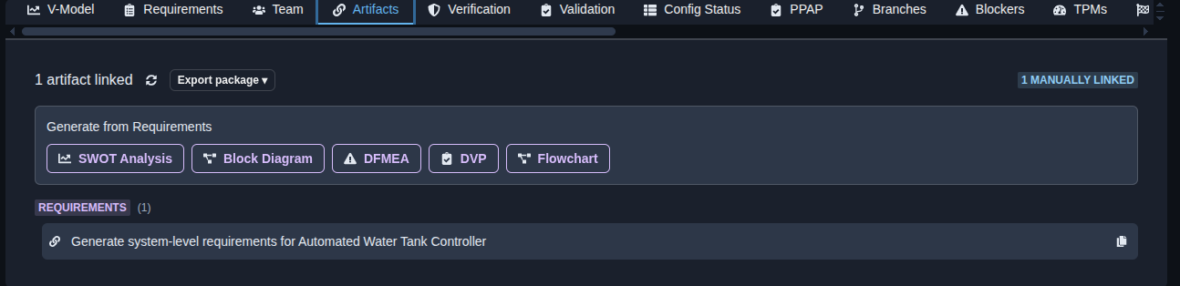
Artifacts. → Open the “Artifacts” tab to review the linked artifacts and requirements for the selected system or node. Use the “Generate from Requirements” options to create a “SWOT Analysis,” “Block Diagram,” “DFMEA,” “DVP,” or “Flowchart,” and use “Export package” to export the artifact package.
▶ Artifacts▼ Artifacts
-
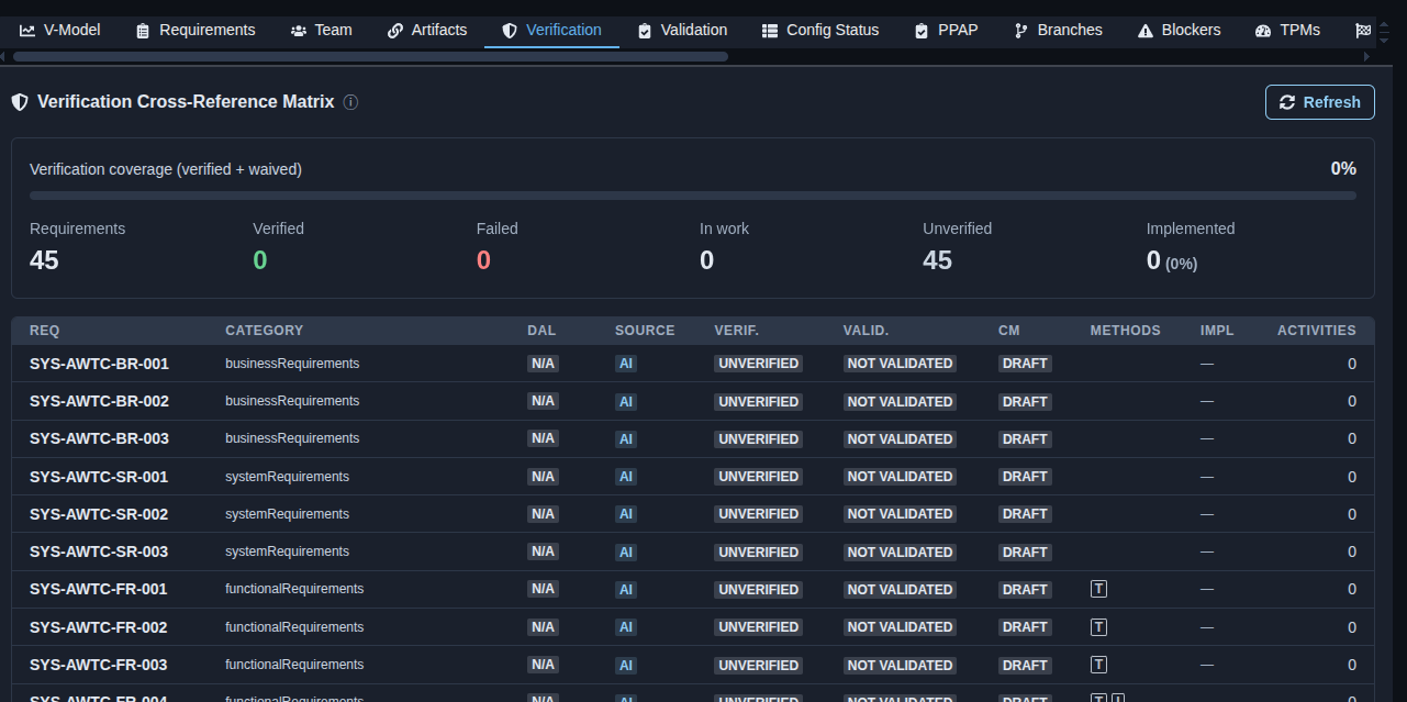
Verification cross-reference matrix. → Open the “Verification” tab to review verification coverage for the system requirements. The matrix shows the total requirements and their verification status, including Verified, Failed, In work, Unverified, and Implemented counts, along with each requirement’s category, DAL, source, verification status, validation status, configuration-management status, verification methods, implementation status, and activities. Click “Refresh” to update the verification matrix with the latest information.
▶ Verification▼ Verification
-
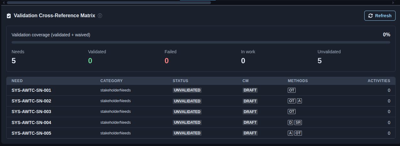
Validation cross-reference matrix. → Open the “Validation” tab to review validation coverage for the system needs. The matrix shows the total needs and their validation status, including Validated, Failed, In work, and Unvalidated counts, along with each need’s category, status, configuration-management status, validation methods, and activities. Click “Refresh” to update the validation matrix with the latest information.
▶ Validation▼ Validation
-
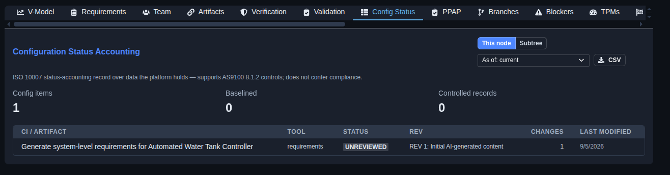
Configuration status. → Open the “Config Status” tab to review the configuration status accounting for the selected node or its subtree. The page shows the number of configuration items, baselined items, and controlled records, along with each configuration item or artifact’s tool, status, revision, number of changes, and last modified date. Use “This node” or “Subtree” to change the scope, select the required “As of” view, and click “CSV” to export the configuration status data.
▶ Configuration▼ Configuration
-
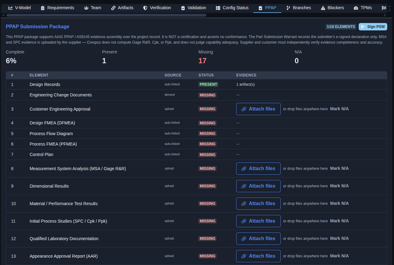
PPAP submission package. → Open the “PPAP” tab to review the PPAP Submission Package, including the overall completion percentage and the number of Present, Missing, and N/A elements. Review each PPAP element, its source, status, and available evidence. For elements requiring supplier-provided evidence, use “Attach files” to upload the required documents or select “Mark N/A” when applicable. Review the linked evidence for each element and use “Sign PSW” to sign the Part Submission Warrant when the package is ready.
▶ PPAP▼ PPAP
-
Branches. → Open the “Branches” tab to review the follow-on branches for the selected node. The page displays any active follow-on branches created when teammates fork a tool artifact at this node; when no active branches exist, it indicates that there are currently no active follow-on branches.
▶ Branches▼ Branches

-
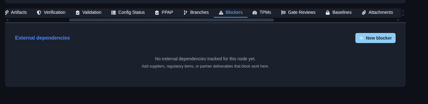
Blockers. → Open the “Blockers” tab to review external dependencies that may block work for the selected node. Review the listed suppliers, regulatory items, or partner deliverables that are being tracked as dependencies, and click “New blocker” to add a new external dependency when required.
▶ Blockers▼ Blockers
-
Technical Performance Measures. → Open the “TPMs” tab to review the Technical Performance Measures for the selected node. The page displays the TPMs currently tracked for the node, and if none exist, it indicates that no TPMs are available yet. Click “+ TPM” to add a Technical Performance Measure and begin tracking its performance margin.
▶ TPMs▼ TPMs

-
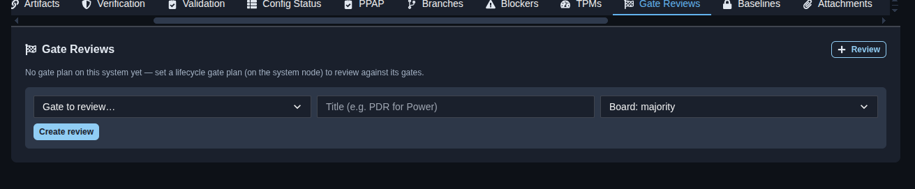
Gate Reviews. → Open the “Gate Reviews” tab to view existing gate reviews or create a new review. Select the gate to review, enter a review title, choose the review board type, and click “Create review” to create the gate review.
▶ Gate Reviews▼ Gate Reviews
-
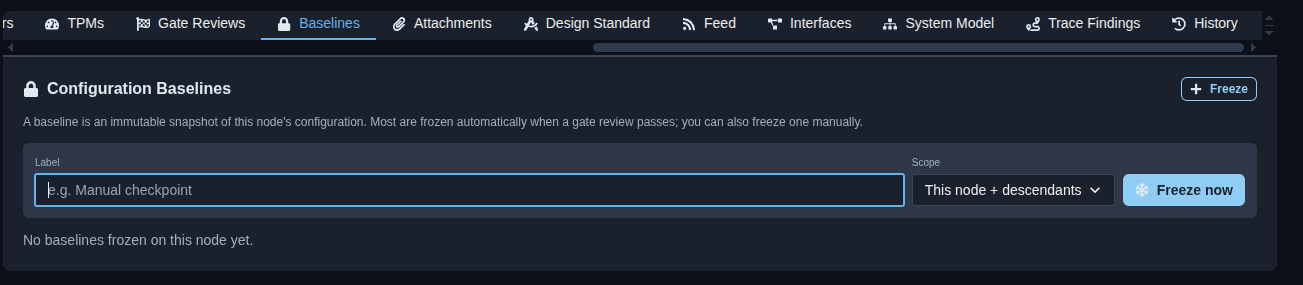
Create a configuration baseline. → Enter a label for the baseline, select the required scope such as “This node + descendants,” and click “Freeze now” to create an immutable snapshot of the node’s configuration. The created baseline is stored under “Configuration Baselines” for configuration control and reference.
▶ Baseline▼ Baseline
-
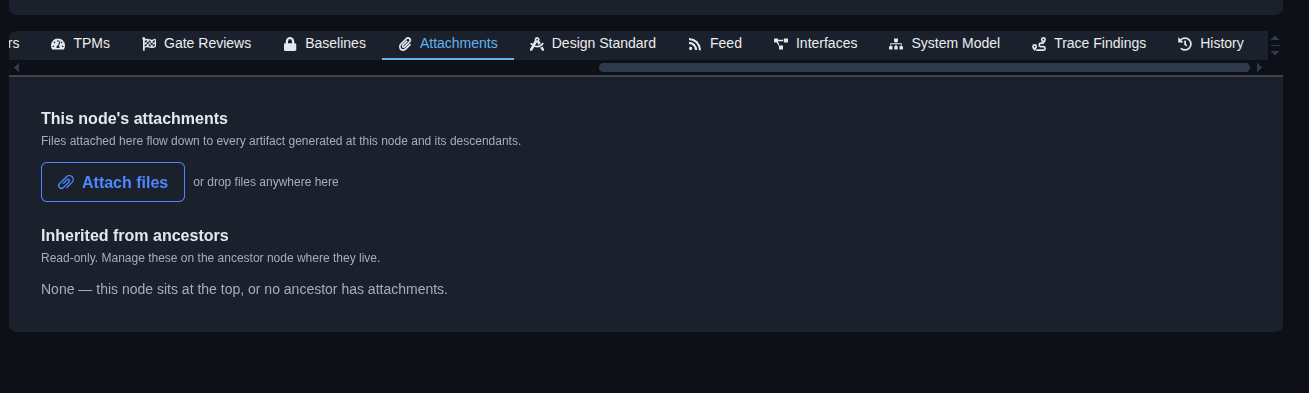
Manage node attachments. → Open the “Attachments” tab to view files attached to the current node. Click “Attach files” or drop files into the attachment area to add files; attachments added to this node flow down to artifacts generated at this node and its descendants. Review any attachments inherited from ancestor nodes, which are read-only here.
▶ Attachments▼ Attachments
-
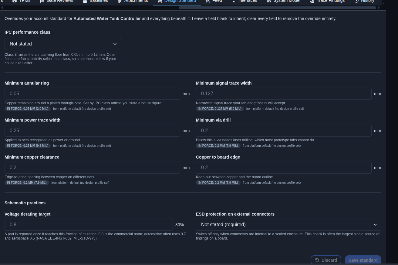
Configure the design standard. → Review or update the design-standard settings for the system, including IPC performance class, minimum annular ring, minimum signal trace width, minimum power trace width, minimum via drill, minimum copper clearance, copper-to-board-edge clearance, voltage derating target, and ESD protection requirements for external connectors. Leave a field blank to inherit the account standard or clear a field to remove the override, then click “Save standard” to apply the settings or “Discard” to cancel the changes.
▶ Design standard▼ Design standard
-
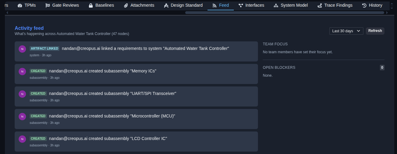
Review the activity feed. → Open the “Feed” tab to review recent activity across the system and its nodes, including events such as artifacts being linked and nodes being created. Use the time-range filter, such as “Last 30 days,” to control the activities shown and click “Refresh” to update the feed. The right side also shows Team Focus and the current number of Open Blockers.
▶ Feed▼ Feed
-
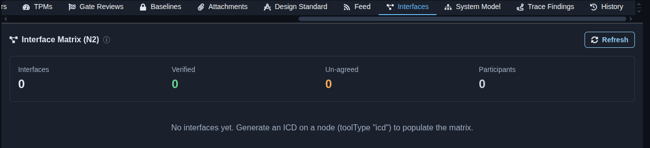
Review the interface matrix. → Open the “Interfaces” tab to review the Interface Matrix (N2), including the total number of Interfaces, Verified interfaces, Un-agreed interfaces, and Participants. If no interfaces are available, the matrix indicates that an ICD must be generated on a node to populate the interface information. Click “Refresh” to update the matrix.
▶ Interface▼ Interface
-
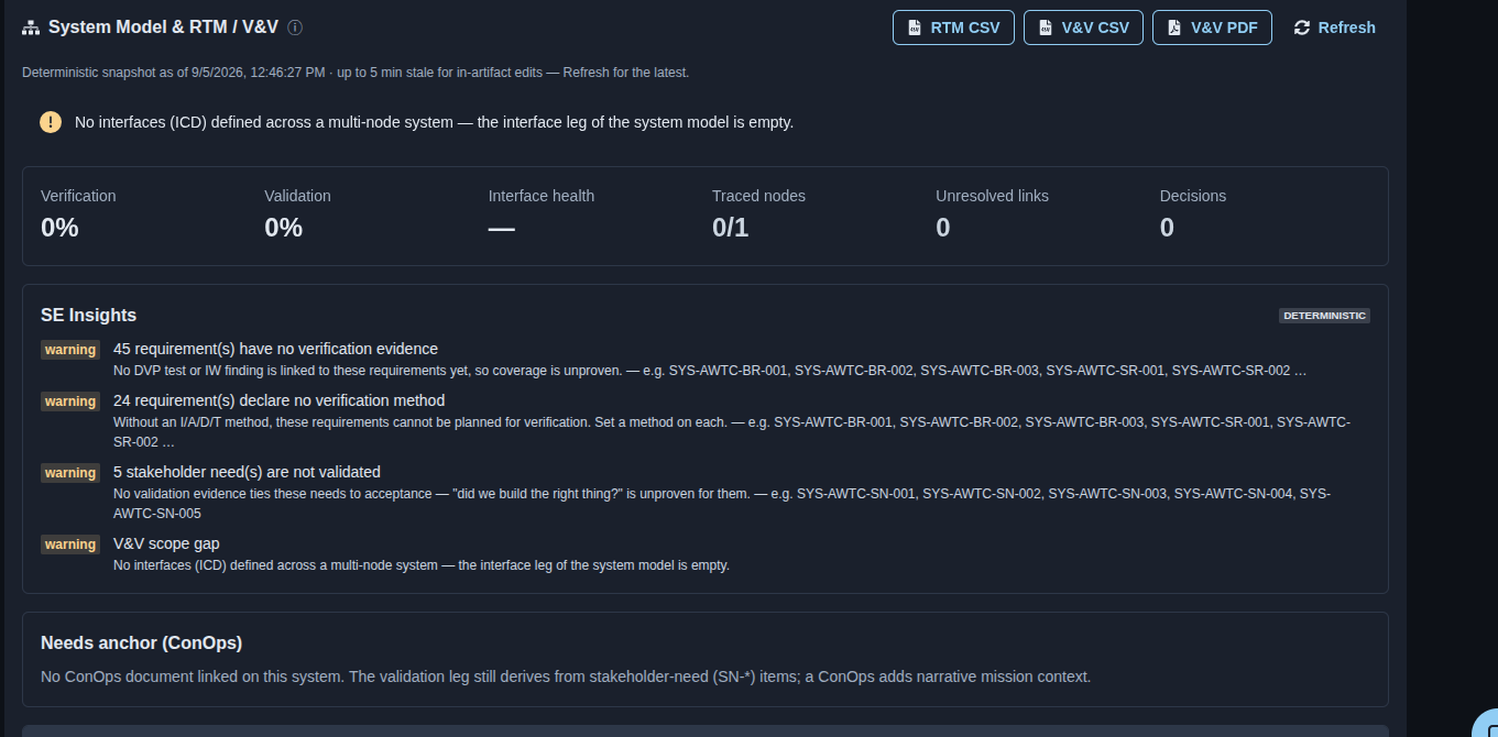
Review the System Model & RTM / V&V. → Open “System Model & RTM / V&V” to review the system-level Verification, Validation, Interface health, Traced nodes, Unresolved links, and Decisions status. Review the “SE Insights” section for warnings related to missing verification evidence, missing verification methods, unvalidated stakeholder needs, and V&V scope gaps. Review the “Needs anchor (ConOps)” section to check whether a ConOps document is linked to the system. Use “RTM CSV”, “V&V CSV”, or “V&V PDF” to export the available traceability and V&V information, and click “Refresh” to update the snapshot.
▶ System model▼ System model
-
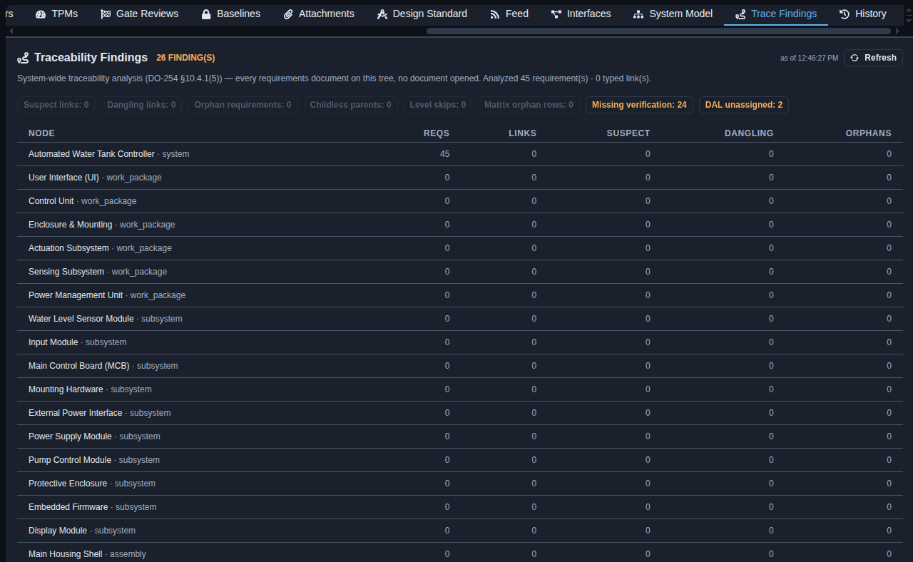
Review the traceability findings. → Open “Trace Findings” to review the system-wide traceability analysis, including the total findings and the counts for Suspect links, Dangling links, Orphan requirements, Childless parents, Level skips, Matrix orphan rows, Missing verification, and DAL unassigned. Review the node-level table showing the number of requirements, links, suspect links, dangling links, and orphan requirements for each node. Click “Refresh” to update the findings.
▶ Trace finding▼ Trace finding
-
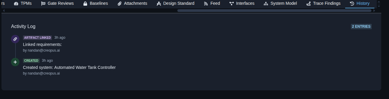
Review the activity history. → Open the “History” tab to review the activity log for the system, including recorded events such as artifacts being linked or unlinked and systems being created, along with the time of each event and the user who performed the action.
▶ History▼ History
-
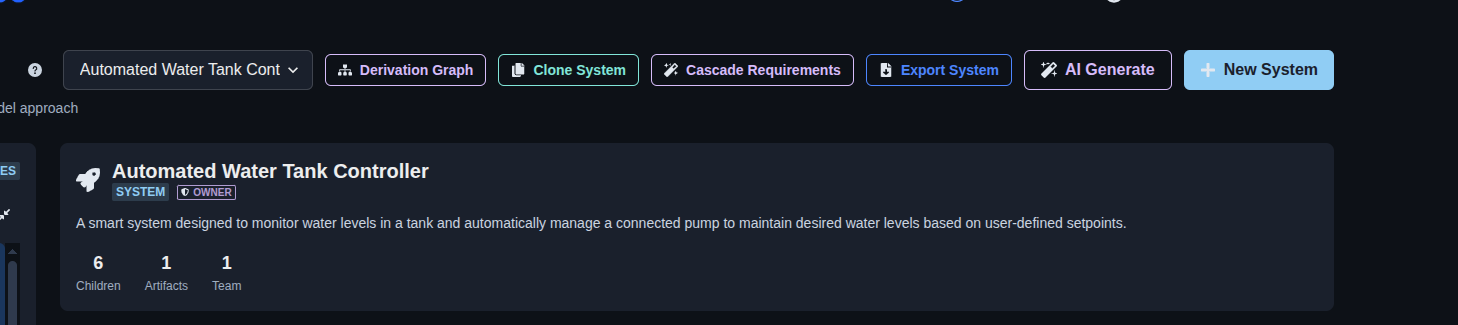
Manage the system hierarchy. → Use the system selector to choose the system you want to work with. Use “Derivation Graph” to view the system relationships, “Clone System” to create a copy of the system hierarchy, “Cascade Requirements” to generate and cascade requirements through the hierarchy, “Export System” to export the system information, “AI Generate” to generate a system hierarchy from a product or system description, or “New System” to create a new top-level system.
▶ Manage system hierarchy▼ Manage system hierarchy
Mechanics
- Recursive five-level V-Model hierarchy · per-node status
- Life-cycle gate plans: Commercial · Aerospace-NASA · NASA KDP · AIAG APQP
- Node tabs: V-Model · Requirements · Team · Artifacts · Verification · Validation · Config Status · PPAP · Branches · Blockers · TPMs · Gate Reviews · Baselines · Attachments · Design Standard · Feed · Interfaces · System Model · Trace Findings · History
- Hierarchy management with Add · Edit · Team access · Link · Delete controls
- Cascade Requirements for propagating requirements through the system hierarchy
- Derivation Graph for requirement derivation and coverage
- Team access with ancestor inheritance
- Verification and Validation cross-reference matrices with coverage status
- Configuration Status with revision and change tracking
- PPAP submission package with evidence tracking and PSW signing
- Blocker tracking for external dependencies
- Technical Performance Measures (TPMs) for node-level performance tracking
- Gate Reviews with configurable review gates and board decisions
- Configuration Baselines with manual freeze and scope selection
- Attachments with inheritance from ancestor nodes
- Design Standard overrides for PCB and schematic design practices
- Activity Feed for system and node-level changes
- Interface Matrix for tracking system interfaces and verification status
- System Model & RTM / V&V with traceability and engineering insights
- Traceability Findings for requirement links, verification gaps, and trace issues
- History for tracking system and node activity
- AI Generate · Clone System · Export System